
Raspberry Pi and General-Purpose Input/Output
Robots are able to sense and interact with the environment through a wide range of components.
So that a robot can make decisions and perform actions, it uses a processor to receive information from and send signals back to the other components.
A standard interface for connecting a single-board computer or microprocessor to other components is through General-Purpose Input/Output (GPIO) pins.
Controlling robots using the Raspberry Pi
Raspberry Pi computers are wonderfully diverse in what they can do. Among the many applications they can be used for, robotics is one of the most exciting and powerful.
Each model of the Raspberry Pi has a set of General-Purpose Input/Output (GPIO) pins along the top edge of the board. These can be used for connecting and communicating with all manner of electronic components, acting as a physical interface between the Raspberry Pi and the outside world. Using the pins, you can program the Raspberry Pi to switch components on and off (output), or receive data from sensors and switches (input).
Raspberry Pi models
Most models of the Raspberry Pi have a 40-pin header, as shown in the image above. Of the 40 pins, 26 are GPIO pins and the others are power or ground pins (plus two ID EEPROM pins, which you should not play with unless you know your stuff!). Any of the GPIO pins can be designated (in software) as an input or output pin and used for a wide range of purposes; whether it is turning on an LED, driving a motor, or sending data to another device, the possibilities are almost endless.
Early models of the Raspberry Pi A and B have a shorter header with 26 pins, as shown below.
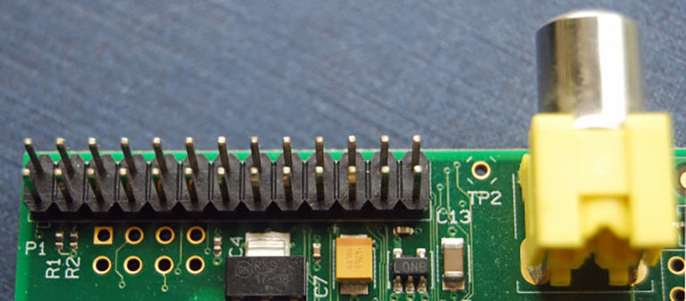
The Raspberry Pi Zero models have unpopulated pins (apart from the Raspberry Pi Zero WH) so there are holes where the GPIO header is located instead of physical pins. This means you need to add a header that includes the pins yourself.
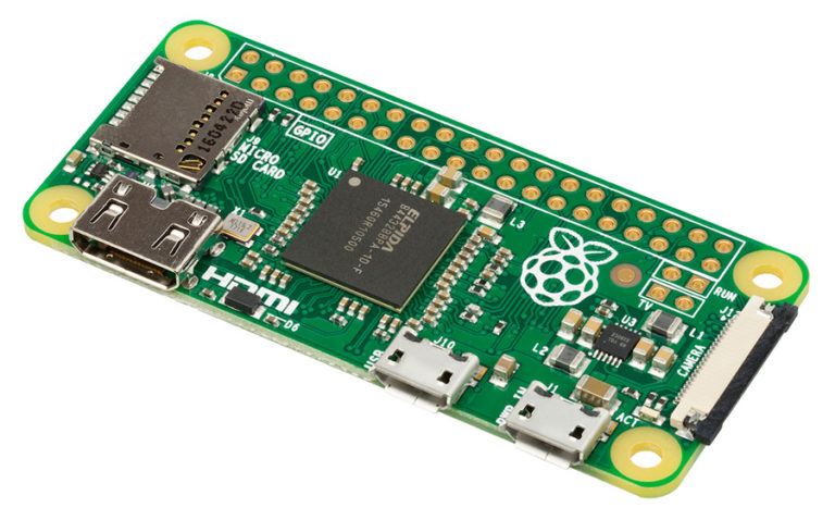
Although it is possible to create a robot buggy with most models of Raspberry Pi, I recommend using a Raspberry Pi 3B, 3B+, or 4. These models allow you to program the Raspberry Pi easily and connect it to another computer or even a smartphone by using the inbuilt WiFi or Bluetooth, rather than needing to plug the Pi physically into a screen or a keyboard and mouse.
GPIO pin numbering
When programming the GPIO pins, there are two different ways to refer to them: GPIO numbering and physical numbering. Throughout this course (and in all our resources) we will refer to the pins using the GPIO numbering scheme. These are the GPIO pins as the computer sees them.
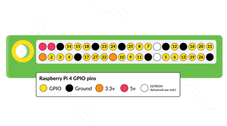
The numbering of the GPIO pins is not in numerical order, instead relating to the numbering on the CPU of the Raspberry Pi, so there is no easy way to remember them. However, you can use a reference board that fits over the pins, a printed reference (like the image above), or a website guide to the GPIO pins to help you.
Voltages
The voltage of a pin is labelled on the reference guide. There are two 5V pins and two 3V3 pins, as well as a number of ground pins (0V), which are unconfigurable. The remaining pins are all general-purpose 3V3 pins, meaning that the outputs are set to 3.3 volts and the inputs are tolerant of 3.3 volts.
A GPIO pin designated as an output pin can be set to high (3.3V) or low (0V). Components are usually attached so that setting the output to high will allow current to flow to them, while setting the output to low won’t.
A GPIO pin that is designated as an input will allow a signal to be received by the Raspberry Pi. The threshold between a high and a low signal is around 1.8V. A voltage between 1.8V and 3.3V will be read by the Raspberry Pi as high; anything lower than 1.8V will be read as low. Do not allow an input voltage above 3.3V, or else you will fry your Pi!
A word of caution
While connecting most components to the GPIO pins is perfectly safe, it’s important to be careful how you wire things up, or you could damage the Raspberry Pi or the components.
A few pieces of general advice:
- Do not attach 3V3 components directly to a 5V pin on the Raspberry Pi, or you may damage the component or your device
- Certain components, such as LEDs, should have resistors to limit the current passing through them
- Do not connect motors directly to the GPIO pins; instead, use a motor controller board or an H-bridge circuit
In the next step, you will look at how to connect the motors to the motor controller board.
Robotics With Raspberry Pi: Build and Program Your First Robot Buggy


Robotics With Raspberry Pi: Build and Program Your First Robot Buggy
Reach your personal and professional goals
Unlock access to hundreds of expert online courses and degrees from top universities and educators to gain accredited qualifications and professional CV-building certificates.
Join over 18 million learners to launch, switch or build upon your career, all at your own pace, across a wide range of topic areas.