Ultrasonic distance sensors
Your robot buggy will use an ultrasonic distance sensor (UDS) to help it navigate the physical world. In this step, you’ll look at how these work.
Ultrasound
A UDS uses ultrasound to measure distances. Sound travels through the air in a wave pattern; measurements are made by examining the properties of the pattern over space and time.
As the sound travels, the particles in the air oscillate back and forth. This is often represented instead as a wave moving up and down on a graph. A sound’s frequency is the number of oscillations per second. Frequency is measured in hertz (Hz); 1Hz corresponds to one oscillation per second.
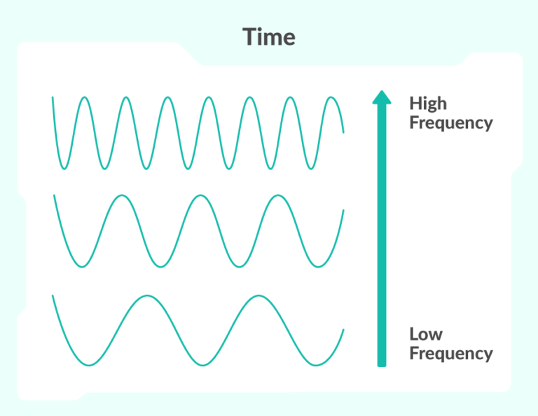
Ultrasound refers to any sound that has a frequency above the range of human hearing. This level varies from person to person, but on average, any sound with a frequency of 20kHz (20,000 oscillations a second) or above is considered ultrasound.
The uses of ultrasound are many: doctors use the sound waves to scan inside human bodies, robots can use them to navigate the world, and engineers use them to reinforce metals by compressing the particles.
Ultrasound and ultrasonic distance sensors
A UDS works by sending out a burst of ultrasound. This sound will travel through air, but reflect back (echo) off surrounding objects. The sensor can detect the echo when it returns.
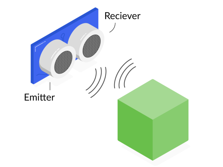
Using a measure of the time between the outgoing burst and the returning echo, and knowing the speed of sound, you can calculate how far away an object is from the sensor.
Commonly, a UDS requires two components to do this: an emitter and a receiver. You can see this in the picture above; the two silver cylinders on the front of the sensor are the emitter and receiver.
A particular advantage of these sensors over other distance measurers, specifically those that use light, is that a UDS is not affected by the colour of the object that the signal reflects off. However, errors can occur if the object can reflect sound away from the receiver.
How to use a UDS
Now that you have a better idea of what a UDS is and how it works, you can move on to a more practical examination of how to use one with your buggy.
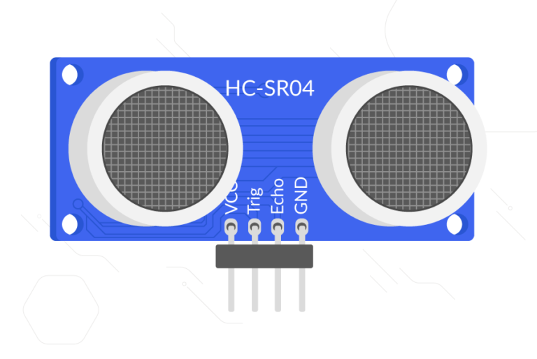
A UDS typically has four pins:
- VCC needs to be connected to a 5V pin, in order to power the device
- Trig is the pin that triggers the emission of the ultrasound burst
- Echo is the pin that provides an output from the device; it outputs at 3.3V or 5V, depending on the UDS model
- GND is the ground pin, used to complete the circuit
If the UDS is 5V-tolerant, this causes some issues because the echo pin will output 5V and the Raspberry Pi can only handle 3.3V. This means you will have to use some resistors to create a voltage divider, also known as a potential divider. Make sure to check the voltage tolerance of your UDS; the HC-SR04 sensor will need a voltage divider. A 3V3-tolerant sensor, such as the HC-SR04P, will work without a voltage divider.
Voltage dividers
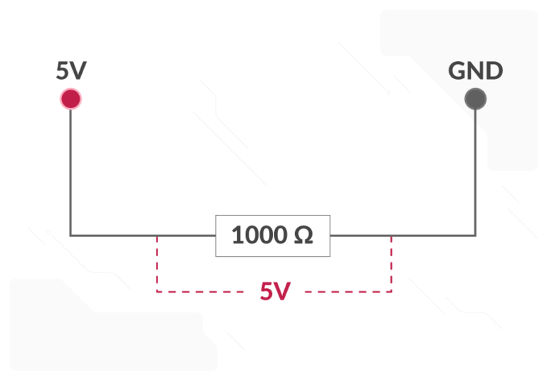
A voltage (or potential) divider can split a voltage into two smaller voltages by using multiple resistors. The diagram below shows a single resistor connected to a 5V pin. The voltage across the resistor is 5V:
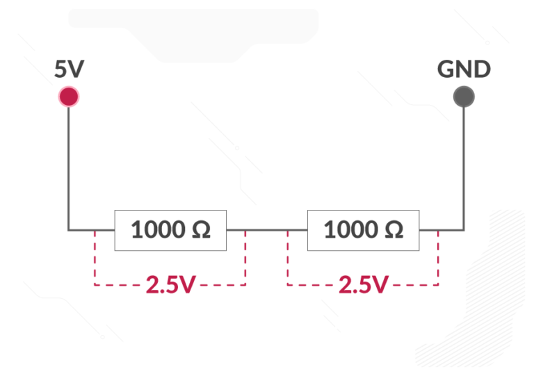
The diagram below shows how the voltage can be split by using two resistors wired in series. As both resistors are the same, the voltage is split equally between the two:
By altering the resistors, you can tailor the voltage across any one of them to be anything you like. Here, you can see that I have split the voltage to give us almost exactly 3.3V across the second resistor:
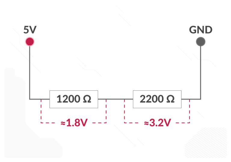
You can use the code below to work out the resistors you need:
R1 = 1200 # Your current resistor (alter this)
Vout = 3.3 # The voltage you are trying to achieve (always 3.3) across the resistor R2
Vin = 5 # The input voltage (always 5)

R2 = (Vout * R1) / (Vin - Vout)

print('The resistor you need is approximately', R2)
The limitations of a UDS
The biggest limitation of this type of sensor comes into play when the object that reflects the ultrasound is very close. In this case, the receiver might not pick up the sound when it is initially reflected off an object, and may instead detect the sound once it has rebounded off another object. This results in an inaccurately high distance reading.
Test your voltage divider
Using the code and formula above, decide what size resistors you would use to limit the voltage to 1V.
Share your thinking and answers in the comments below.
Robotics With Raspberry Pi: Build and Program Your First Robot Buggy


Robotics With Raspberry Pi: Build and Program Your First Robot Buggy
Reach your personal and professional goals
Unlock access to hundreds of expert online courses and degrees from top universities and educators to gain accredited qualifications and professional CV-building certificates.
Join over 18 million learners to launch, switch or build upon your career, all at your own pace, across a wide range of topic areas.