
True and False in Logic
In this step we are going to introduce the concepts of True and False in logic and explain how these are denoted as signals of 1 and 0. We will also have a go at building simple versions of the two most basic logic gates, AND and OR.
True and False
You will already know that computers are very good at doing millions of calculations very quickly, but did you know that they are always dealing with one basic question: True or False (which essentially means on or off)? You’ve seen the symbol on the switch of most electrical items and computers that looks like this:
This basic switch symbol, which looks like a 1 and a 0, has come to mean on/off and could be interpreted as representing the entire way in which computers work. The 1 means True (or on) and the 0 means False (or off). If we take this right back to the physical way in which computers work, the 1 represents a high voltage and the 0 represents a low voltage. These voltages control transistors – electrical components which act as an electrically controlled switch.
Before we start looking at the way in which we express this, it may be useful to consider this table, which lists four of the ways that computer scientists and educators express this same concept.
| True | False |
|---|---|
| On | Off |
| Current flowing | Current not flowing |
| 1 | 0 |
In programming we refer to variables which can only have two possible states, True or False, as having the Boolean data type.
By combining millions of these on/off switches, the computer can handle very complex conditions to tackle very complex calculations. But let’s start at the beginning, by considering how we handle one condition.
Logic Gates
We can represent this process in diagrammatic form by using logic gates to represent the flow of electricity through a transistor. A logic gate is an electric circuit, usually with two inputs and an output. It receives two incoming electric currents, determines whether they are True or False (on or off), and sends on a new, outgoing electric current depending on what it finds. The process of determining the output based on the inputs like this is known as Boolean logic.
The AND gate
This is an AND logic gate, which represents a small circuit configured in a particular way to give a particular result. You can see the inputs on the left represented by lines going into the AND logic gate symbol. What do you think this means?
The AND gate has two inputs and one output. Both have to be True (or on) to produce an output of True. In the example above both inputs are set to True, which results in a True output.
What if only one was True? Like this:
What do you think the output (denoted by X here) would be this time?
In the case of an AND gate, if only one of the inputs was switched on then the output is 0. And if neither input is switched on, you would be right in assuming that there is again an output of 0. Both the first input and the second input have to be 1 to achieve a True (or 1, or on) output.
The OR gate
So, an AND gate only switches on when both inputs are on. What about if we want the output to be on when at least one of the inputs is on? This is called an OR gate. In order for the gate to produce an output of True, there must be a current from at least one input. Can you predict what the output would be if the inputs were 0 and 1 in an OR gate?
Why not use Circuitverse to test if your predictions are correct? Circuitverse is a very useful and free online tool which simulates logic circuits. Go to Circuitverse and begin by clicking ‘Launch Simulator’. Choose two inputs, one output, and the OR gate, and then try toggling the different options to switch the two inputs on and off. By clicking on the dots on the side of the symbols and dragging your mouse you can join the inputs to the logic gate symbol and the logic gate symbol to the output to simulate the flow of current in the circuit. You will see that the output changes depending on your choice of input.
Your OR logic gate, with inputs of 1 and 0, should look like this:
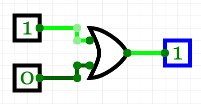 symbol, joined together. The inputs (two lines coming in from the left) are set to 1 and 0. The output (a line out from the tip of the > ) is 1.”>
In the next step we will look at truth tables, which are tables that provide complete summaries of the inputs and outputs of logic gates and circuits.
Understanding Maths and Logic in Computer Science


Understanding Maths and Logic in Computer Science
Reach your personal and professional goals
Unlock access to hundreds of expert online courses and degrees from top universities and educators to gain accredited qualifications and professional CV-building certificates.
Join over 18 million learners to launch, switch or build upon your career, all at your own pace, across a wide range of topic areas.

