
How to design a real-time computing system
In this article, we will walk you through the creation of a real-time algorithm: an alarm-triggering algorithm for an automated greenhouse system.
How to craft an algorithm
All computer systems take input, process data, and output results. Algorithms are part of that middle step; they direct the processing a computer system performs to create meaningful data, for users or for other systems.
Real-time computing algorithms differ from other computing algorithms in two key ways: they are time-bound, and they are event-driven. The algorithm must be performed at a specific time, and it is triggered by an event rather than being run manually by a user.
When you create algorithms, you need to ask three key questions:
- What are the inputs?
- What conditions or processes need to be included?
- What output do you want if those conditions are met?
For a real-time computing algorithm, you should also ask:
- What will trigger the algorithm?
How to design an algorithm to trigger an alert
Going back to the earlier example, we will walk you through the creation of an algorithm to trigger the warning alarm in my automated greenhouse. The persona used in that design will want some way of knowing when there is a system fault or some other risk to their plants.
Let’s begin by answering those questions.
1. What are the inputs?
An input to an algorithm is different to an input to a computer system. Inputs to a computer system are manual or automatic actions linked to devices. Inputs to algorithms are instead pieces of data that already exist within the system, and that the algorithm will use for processing or comparisons.
This algorithm will have three inputs: the current temperature, a preset low value, and a preset high value.
The preset values will be set by the user, but for the purpose of this algorithm design, we will assume they already exist.
2. What conditions or processes need to be implemented?
The algorithm needs to perform two conditional checks, linked with an OR operator. It should check whether the current temperature is lower than the low value OR whether the current temperature is higher than the high value.
3. What output do you want if those conditions are met?
If either of the above conditions is True (all conditional operations return a Boolean value), the system should trigger the alarm. In general, an alarm should be perceptible to more than one sense. Just using light would require you to be in sight of the greenhouse, and just playing a sound risk that sound getting drowned out by other noise. This alarm should use both.
What will trigger the algorithm?
Event-driven systems use events generated by software and hardware to trigger logical operations. You should consider what event could be used to trigger this algorithm.
In the greenhouse, the temperature sensor will be taking readings regularly to monitor the environment; each reading is an event. The alarm algorithm could be triggered immediately after the reading has been captured. If the condition is met, the alarm will turn on.
You can now sketch out the algorithm using flow charts. In event-driven systems, the developer writes event handlers, which are subroutines that are called when an event occurs. This is what we will create now.
A flow chart for the alarm
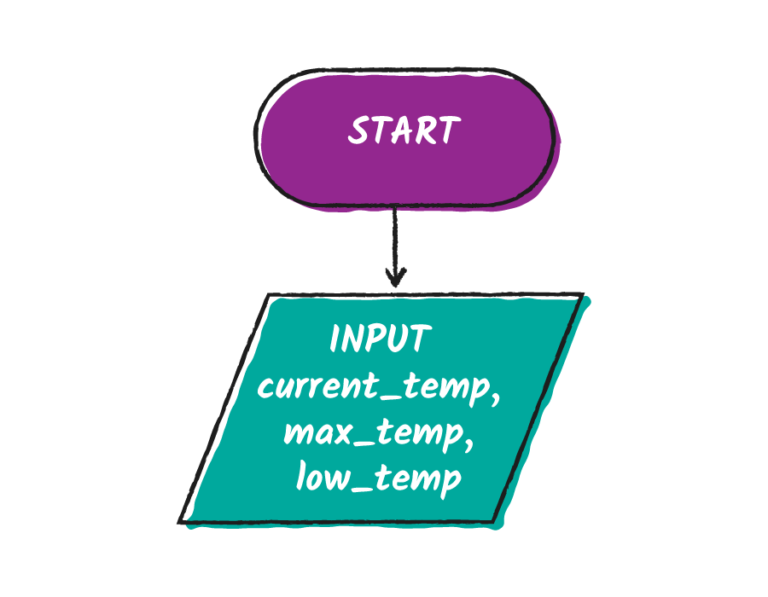
We are going to start by declaring the inputs. When we implement this algorithm, it will need to access the registers that are storing these pieces of data. For the moment, we can just note down that the pieces of data will be input into the algorithm.
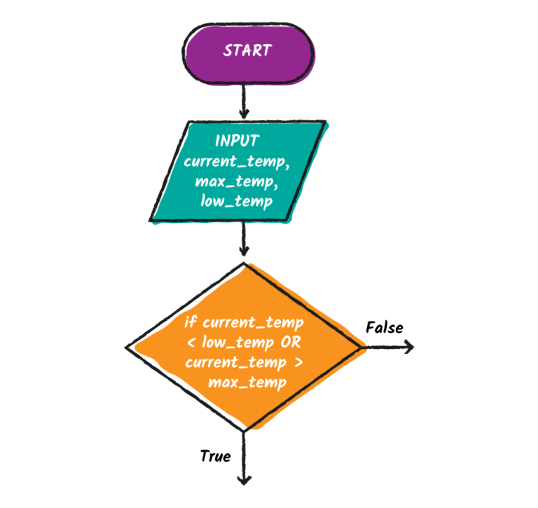
Next, we add two conditional statements, linked with an OR operator. This creates two branches in the algorithm: one where the conditions are True and the other where they are False.
If the condition is True, we want the LED to turn on and the buzzer alarm to trigger. Then the algorithm can stop.
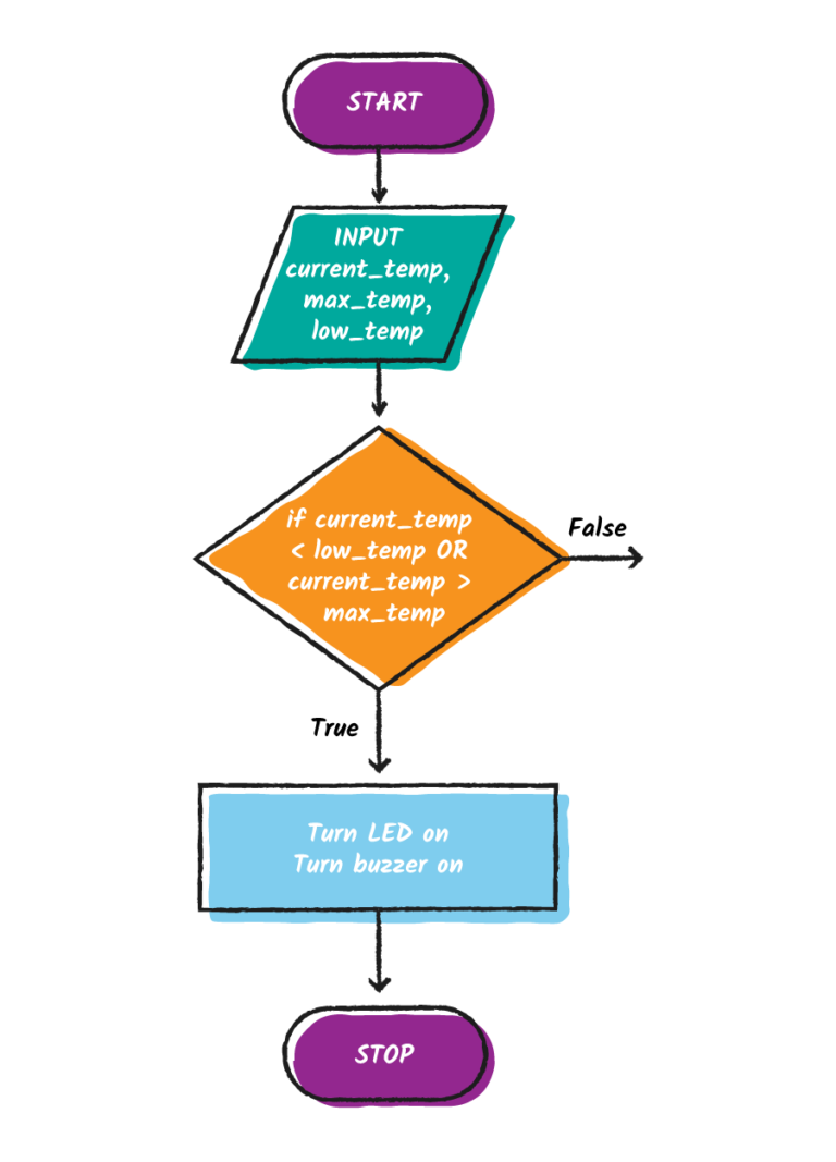
However, we should also think about how the alarm is reset. The current algorithm will turn the two components on, but it will never turn them back off. For this, we can use the other branch of the algorithm; if the condition is False, the greenhouse has returned to normal temperature levels, and the alarm can turn off.
Extrapolating this algorithm
Now that we have made one algorithm to trigger an alarm, you can use this same process to create an alarm feature for another system.
- Using the same process shown above, create an algorithm that will trigger an alarm in a smartwatch
- Upload an image of your flow chart to a service such as Imgur or a similar sharing platform. You will have to right-click to open in a new tab, or use the back button to return to the course.
- Share a link to the flow chart and your answers to the key questions above with your fellow learners
Design and Prototype Embedded Computer Systems


Design and Prototype Embedded Computer Systems
Reach your personal and professional goals
Unlock access to hundreds of expert online courses and degrees from top universities and educators to gain accredited qualifications and professional CV-building certificates.
Join over 18 million learners to launch, switch or build upon your career, all at your own pace, across a wide range of topic areas.