
Line sensors and how to use them
In this step you will investigate how a line sensor operates and how it detects a line. I will be using the TCRT5000 IR sensor as my example, but the learning can apply to other line sensors as well. This knowledge will help you design and program a line-following algorithm later in the week.
Infrared (IR) detection
Line sensors detect the presence of a black line by emitting infrared (IR) light and detecting the light levels that return to the sensor. They do this using two components: an emitter and a light sensor (receiver).
You can see an example TCRT5000 line sensor below. Your components may be laid out differently (all on one side, for example), but the components I will discuss will be present on most line sensors.
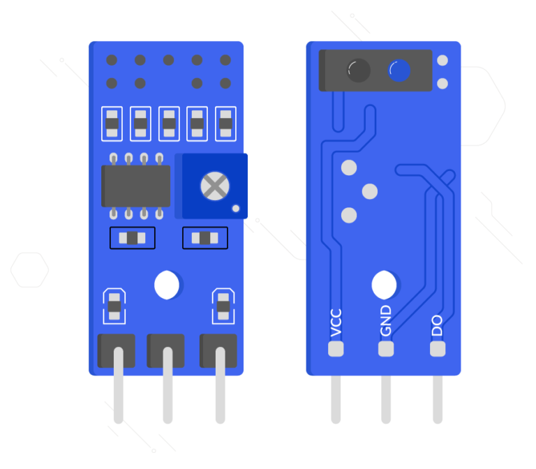
On the top right-hand side of the image you can see two circular components that look a bit like LEDs. The blue one is the IR emitter and the black one is the receiver. These devices also have a component called a potentiometer, which adjusts the device’s threshold. This is done by using a screwdriver to turn the white dial that looks like a cross on the left-hand side of the image.
The device will emit IR light, and the sensor will capture the light level that is reflected from the surface underneath it. Some line sensors have two types of output: analogue and digital. The analogue output is not always present, but will return a constant reading of the light levels the sensor is detecting. Analogue signals need to be converted to digital before a Raspberry Pi can use them. The digital output results from a comparison of the light levels against a threshold level that is adjusted by turning the potentiometer. If the sensor does not receive enough light to surpass the threshold value, the digital output will be high (1). If enough light is received and the threshold value is surpassed, the pin will be set to low (0).
The set-up of these devices may seem a bit topsy-turvy at first, but it makes more sense when you consider that the sensor is designed to detect black lines. A black line will not reflect as much light, so the output will be set to high (1) when a black surface is underneath.
How to use a line sensor
Now that you know a bit more how a line sensor works, you should learn how to use one.
The line sensor also has an array of pins, some of which you will have to connect to the Raspberry Pi you are using:
VCCneeds to be connected to a voltage in between 3.3 and 5V, to power the deviceGNDis the ground pin that is required to complete the circuitAOis the analogue output (this will not work with the Raspberry Pi)DOis the digital output pin (this will work with the Raspberry Pi)
The VCC pin here can take a range of voltages, so potential dividers are not necessary. It is also worth noting that the AO pin does not feature on all line sensors.
Two sensors are better than one
You can create a line-following robot with only one sensor, as this is enough to detect a line underneath the robot. If the robot strays from the line, though, it is very difficult to work out which way it needs to turn to find the line again.
To solve this problem, you can use more than one sensor. If you add a second sensor, and spread the sensors out evenly on either side of the caster wheel, the information gathered from the sensors will allow your robot to find the line again.
If the line is in the centre of the robot, both sensors will return a 0 from their digital pins, as they are both over the white background.
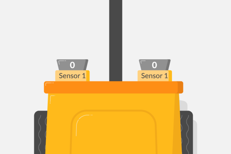
However, if the robot moves to the right, the left sensor will eventually cross onto the line, changing its output to a 1. When this happens, the robot should correct its course and turn left. Once the sensor returns to a 0 value, we know that the line is back in the middle of the robot.
The same applies when the robot turns too far left; the right sensor will move over the line and change its reading. The robot should then turn right to the right to correct itself.
Discussion
You can use even more than two sensors if you want; some designs use three or four.
How would a third sensor in the centre of the robot impact the way it moves?
What difference do the extra sensors make?
Share your thoughts in the comments section.
Robotics With Raspberry Pi: Build and Program Your First Robot Buggy


Robotics With Raspberry Pi: Build and Program Your First Robot Buggy
Reach your personal and professional goals
Unlock access to hundreds of expert online courses and degrees from top universities and educators to gain accredited qualifications and professional CV-building certificates.
Join over 18 million learners to launch, switch or build upon your career, all at your own pace, across a wide range of topic areas.