Skip main navigation

New offer! Get 30% off your first 2 months of Unlimited Monthly. Start your subscription for just £35.99 £24.99. New subscribers only T&Cs apply

Find out more

Analysis: Centres of gravity of composite bodies

If you know the location of the centre of gravity of each component of an object you can find the overall centre of gravity of the whole thing.
9.3
We learned earlier that a plane might crash if its centre of gravity is outside permissible limits. How can you check it? You can use the method of composite bodies.
23.6
This table shows how to find the CG, that is the centre of gravity, of an empty aircraft by weighing the load on each wheel. The location of the CG is obtained by dividing the total moment by the total weight. More on this later. But, how do you check the CG position for each flight when the numbers of passengers and the amount of baggage and fuel might vary? There is a standard calculation and, to implement it, we can use a table like this. There are several sets of calculations here. One with just the pilot, one fully loaded, and others with various amounts of fuel. It must be OK with all of these scenarios if the aircraft is going to be safe.
73.6
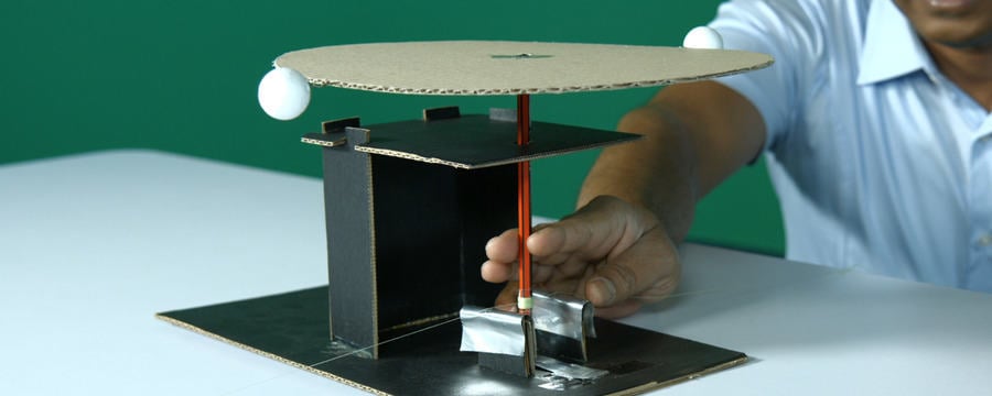
The table assumes that we know the weight and CG of each component. Together, they make up our composite body. We’ve already got the weight and the CG of the bare aircraft by weight. We can now add the effect of having a pilot, a passenger, baggage, and fuel. These are the components of our composite body. We did an experiment with composite bodies. Our one was made up of squares, triangles, and circles. We can find the weight and the CG of each of these components, then combine them. But we’re going to start with a simpler example. Suppose we had two spheres connected by a weightless bar. One sphere is twice the mass, hence twice the weight of the other.
130.6
Here are two free-body diagrams. One shows the two weights. The other shows a combined weight at the centre of gravity. Notice that the CG is not in the middle. It is nearer the larger mass. But how much nearer? We could find the position experimentally by supporting it and finding the point of balance. But that is sometimes impractical. In that case, we can calculate the position. Here’s how. These two representations must be equivalent, which means that they must generate the same force in any direction, and must generate the same moment about any axis. We can express this mathematically. It’s related to equilibrium, so you won’t be surprised to learn that you can check for equivalence by these equations.
189
Firstly, sum of the forces in the y direction on diagram one equals sum of the forces in the y direction on diagram two. This gives us the total weight. Next, we can use the fact that sum of the moments about our point on diagram one must equal sum of the moments about the same point on diagram two. This locates the centre of gravity along the bar, pause the video, and uses equations to find the expressions for w, the total weight, and x, its position along the bar. You could take moments anywhere, so long as the point is the same on both diagrams. Moments about the centre of the left-hand sphere work well here.
250.5
It’s easy to find the total weight. We get W equals W1 plus W2. It’s slightly more complicated to find the x-coordinate of the centre of gravity. Here’s what you do. Take sum of the moments about the left-hand sphere on diagram one, and put it equal to sum of the moments about the same point on diagram two. If you would like to follow the development of this, pause the video and look at each of the lines of the explanation. You can see that the final result is x equals (2/3)L, which is 2/3 of the distance between the two spheres. All this can be summed up in three equations.
301.1
Capital X, capital Y, and capital Z are coordinates of the centroid of the complete body. XC, YC, and ZC are coordinates of the centroid of each component. W represents the weight of each component. For more complicated objects, like an aeroplane, you can use a table to keep track of the calculations. The summations in the equation are easily found from the table. To get the location of the centroid, you just divide one total by the other, which is what you will do next. It will be described in the design task. Now you’ve got the method sorted out. You can use it to predict where to add weight to a paper aeroplane to make it fly.

If you know the location of the centre of gravity of each component of an object you can find the overall centre of gravity of the whole thing.

You do it by taking moments.

We’ll use the method on composite objects where the components are rectangles, circles or triangles. We know the location of the centre of gravity for all of these.

If you know calculus you can apply this method to a wide range of geometric shapes. For example you can prove the standard result for a triangle. But that’s for another time.

For now we’ll stick with simple shapes and show you how to keep track of your working by using a table. A table suits a spreadsheet perfectly.

Talking points

  • What do you think are the benefits of a table when using the method of composite bodies?
  • Under what the circumstances, if any, would you not use a table?
This article is from the free online

Through Engineers' Eyes: Engineering Mechanics by Experiment, Analysis and Design
Created by
FutureLearn - Learning For Life

Reach your personal and professional goals

Unlock access to hundreds of expert online courses and degrees from top universities and educators to gain accredited qualifications and professional CV-building certificates.

Join over 18 million learners to launch, switch or build upon your career, all at your own pace, across a wide range of topic areas.

Start Learning now